PEMAC® Report
PEMAC® Report provides quick and accurate information on pending problems. Input to PEMAC® Report is R-Files generated by the various systems in the MIVA® product series. The R-files are about 7 kB each and can be accessed online via LAN and the Internet. The files can also be transferred via e-mail attachments and USB sticks to PEMAC® Report.
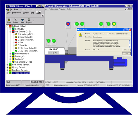 Machine condition status is highlighted in green, yellow, red and blue on the PC screen. A quick glance on the screen gives immediate information on pending problems. Installing screens at strategic locations in the plant such as in the control room and in the entrance to the maintenance office keeps everybody posted on changes in machine condition. The same screen is also available on other PC clients on the LAN and to external expertise via Internet.
Definition of Condition Status
PEMAC® Report displays color coded condition status at different levels:
- Plant status
- Machine status
- Measure point status
- Parameter status
Status at a certain level is a function of status at the levels below. Status for normal condition is defined by the Standard Machine that is assigned to the actual machine. The color codes are the same regardless of the level:
| Code | Status | Condition | Failure Risk | Action |
| Good | Within normal variations | None | None | |
| Satisfactory | Minor discrepancy from normal | Negligible | Pay attention | |
| Unsatisfactory | Major discrepancy from normal | Pending | Analyze and decide | |
| Unacceptable | Max limit values exceeded | Imminent | Analyze and plan shut down |
Application example
This section will give an example on how PEMAC® Report could be used to control maintenance activities on machinery in a plant. PEMAC® Report is configured with clear text messages, which pop up to alert maintenance activities when alarm breaches.
The alarm is sent directly to the control room via relays in DAU. Machine condition is continuously updated on the PC Screen, which is set up in e.g. the Maintenance entrance. The PC Screen is connected online to the MIVA® Online system via LAN. Actual machine condition for the whole plant is displayed on the PC screen and updated every of 5 minutes. Personnel passing the PC screen will immediately get an overview of the situation.
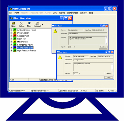 In this example the PC screen shows acceptable machine status for all plant sections except for two of them. One section has unacceptable status (blue) and one has unsatisfactory status (red). Clear text messages have popped up on the screen for each machine causing alarm.
The message on the top states the decanter in the Waste water plant has Bowl unbalance of such magnitude that it requires immediate action. The repeat rate of the alarm is 100%.
The message at the bottom states that it has been generated by the Milk Clarifier in the Cheese Plant. It says “Investigate bearing condition” and has a repeat rate of 45%. The low repeat rate indicates that alarm has been on/off since the first time it was given.
Based on these messages it is quite obvious that the machine in the Waste water plant has an acute condition that must be taken care of immediately. The machine in the Cheese Plant is not in an acute condition but has frequent bearing indications that must be followed more closely. Service on this machine can be scheduled to a suitable time in production.
In addition to above information, that is easily available to anyone passing the PC Screen, a number of reports are also available that can be used for manual evaluation and support of the diagnosis made by the system. Samples of the reports are shown in next section.
Report summary
PEMAC Report offers a number of reports that can be used to support maintainance actions. Samples of reports are given below.
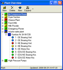 Plant Overview Shows plants and machinery in a tree structure. Status of a plant inherits worst status of all machines in the plant. The plant can be expanded to show all machines in the plant. A machine can be expanded to show all measure points. |
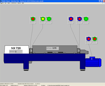 Machine View The machine view shows a picture of the machine and its measure points. |
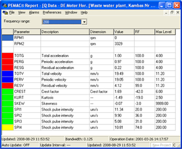 Q-Report One report is available for each measure point and operation. The report shows status of each parameter. |
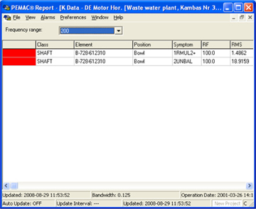 K-Report Shows condition of machine components and symptoms generated by a component such as bearings, shafts etc. The component deviating most from normal values are listed first. Deviations far above normal are red. |
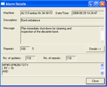 Alarm message Describes cause of alarm and recommends actions in clear text. Text and conditions for sending up a message can be programmed by the user. A counter is incremented each time a message pops up. The value is shown in the Repeats field. A value of 100% means alarm is on continuously. |
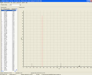 F-Report One report is available for each measure point and operation. The report shows the 50 highest peaks in the spectra. |
Standard Machine Module
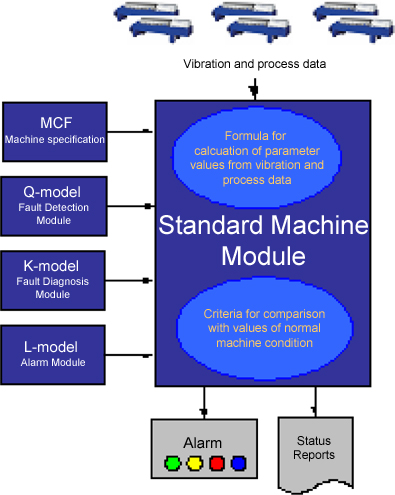 MIVA® Online is automatically evaluating and diagnosing machine condition and the condition of machine components by comparing measured parameter values on a machine with the corresponding parameter values of a “Standard Machine”. All Standard Machines required by MIVA® Online in a specific situation are stored in a set-up file called Standard Machine Module (SMM). In the following we will use the abbreviation “SMM” both for the module itself and for a specific standard machine in the module.
The SMM define limits for normal and acceptable variations in machine condition. It contains configuration files and data models with instructions and criteria for fault detection and fault diagnosis. Machine status and the status of machine components such as rotating shafts, bearings, gears etc is defined by comparing the measured parameter values with values of the SMM. See above under “Definition of condition status”.
Steady improvement of the SMM through feedback of data and experience
Criteria for fault recognition can be set according to ISO Standards. Although this may be a good way to start monitoring on a machine it is definitely limiting the fault detecting and fault diagnosing functions of MIVA® Online.
 ISO Criteria may highlight faults like unbalanced and misaligned shafts but it will definitely not be enough to detect bearing defects, contaminated lubrication oil, gear problems and other similar problems of a machine. This requires other types of parameter values than the one used by ISO Standards.
MIVA® Online is using a over 65 parameter values on each point to detect and diagnose faults. All these parameter values require criteria for normal and acceptable condition. To create reliable criteria is usually a long process which requires feedback of data and reports from evaluation reporting and service actions. This is where the SMM has an important role in MIVA Online. All accumulated experience from machines will be stored in the SMM and used to improve the reliability of future reports. Because SMM apply to a class of machines or to a specific machine type it can be applied also to other individuals of this class or machine type from day one.
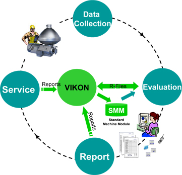
VIKON is offering services for development and fine tuning of the SMM as a part of the PEMAC® Operation Services. This service can be provided in the background without interrupting the monitoring. A typical “learning” cycle for the SMM ranges from a few months to years depending on complexity of the models and the number of machines using the same SMM.
 Parameter Values and Data Models
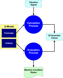
Mathematical and logical models are used by the SMM to define status of machine and machine components. We call these models the “Q-Model” and the “K-Model”. These models are specifically developed for vibration analysis. Another model called “L-model” is a logical model combining parameter values from both the Q-model and the K model to identify and diagnose faults. A well tuned SMM can use the L-model to display messages with recommended maintenance actions in clear text.
The Q-Model
The Q-model is used for analysis of discrepancy in vibration condition between the actual machine and the SMM. Unacceptable discrepancy is interpreted as a change in condition and generates alarm and a report stating alarm status and status of parameter values causing the alarm.
The influence of main vibration sources on measured q-parameter values are illustrated in the following table. In this table stands V for vibration velocity and G for acceleration. Both these are used for fault detection.
| Main source | Q-parameter | Comments |
|
Rotating forces |
TOTG |
Monitors the total velocity amplitude (V) and the total acceleration amplitude (G) in a specified frequency range and the parts of them that is caused by periodic vibration. Typical sources are unbalance and gear mesh problems. The value PERV is also measured for the signal envelope EDU. (1) ISO Standards use TOTV (mm/s rms) in the 1000 Hz range to define vibration severity. |
|
Shocks |
CREST |
Sensitive to transients in the vibration signal. Typical sources are defective bearings, defective gears, looseness etc. |
|
Friction forces |
SPI1 |
Estimates the noise carpet energy in a vibration signal. Typical examples of carpet energy sources are: Defective bearings, rub, poor gear condition, inappropriate lubrication. |
 The K-Model
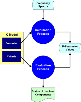
The K-model is used for identification of faulty machine components by analyzing the discrepancy between actual vibration measurements and the SMM. A K-parameter represents a symptom in vibration spectra (frequency pattern) related to a specific machine component such as a shaft or a bearing.
The SMM constitutes a number of possible symptoms and criteria for normal condition of each machine component. The discrepancy between measured symptoms and symptoms defined by the SMM provides accurate diagnosis of defective machine components.
The K-model contains parameter formulas and criteria for calculation and assessment symptoms belonging to the machine components. Each parameter describes a pattern in the vibration spectra, which is generated under normal conditions and when a fault has developed. The spectral power of this pattern is the value of the K-parameter. The model contains also criteria for normal variations of the K-parameter values.
SMM for a Class of machines
When starting a condition monitoring program it is usually not possible to find values of the Q-parameters other than TOTV (velocity rms amplitude) in the 1000 Hz range. VIKON may have SMM for certain machine types and in this case reference values may be defined for all parameters. However, when nothing is known about the machine, except the machine class to which it belongs, it is still possible to get a good reference by using the ISO 2373 standard.
The following shows severity ranges and examples of their applications to different classes of machines according to ISO 2372..
| Classes of machines as defined by ISO 2372 | |||
| Class I - Individual parts of engines and machines, integrally connected with the complete machine in its normal operating condition. (Production electrical motors of up to 15 kW are typical examples of machines in this category.) | Class II - Medium-sized machines (typically, electric motors with 15 to 75 kW output) without special foundations, rigidly mounted engines, or machines on special foundations (up to 300 kW). | Class III - Large prime movers and other large machines with rotating masses mounted on rigid and heavy foundations which are relatively stiff in the direction of vibration measurement. | Class IV - Large prime movers and other large machines with rotating masses mounted on foundations which are relatively soft in the direction of vibration measurement (for example, turbo-generator sets, especially those with lightweight substructures) |
| Vibration Severity mm/s rms |
Small Machines | Medium Machines | Large Machines | |
| Class I | Class II | Class III Rigid Support |
Class IV Flexible Support |
|
| 0.28 | ||||
| 0.45 | ||||
| 0.71 | ||||
| 1.12 | ||||
| 1.80 | ||||
| 2.80 | ||||
| 4.50 | ||||
| 7.10 | ||||
| 11.20 | ||||
| 18.00 | ||||
| 28.00 | ||||
| 45.00 | ||||
| 71.00 | ||||
VIKON reserves the right to alter any part of the above publication due to eventual omissions or errors in the publishing and does not assume any liability for errors or omissions. To ensure correct information please refer directly to the ISO 2372 Standard.
Above diagram shows vibration severity ranges and examples of their applications to different classes of machines according to ISO 2372. Colored areas for unacceptable, unsatisfactory and acceptable vibration are recommendations only. Colours may be interpreted the following way:
Green - Normal condition
Yellow - Satisfactory condition
Red - Unsatisfactory condition
Blue - Unacceptable condition

