
ROBAL® software for rotor balancing
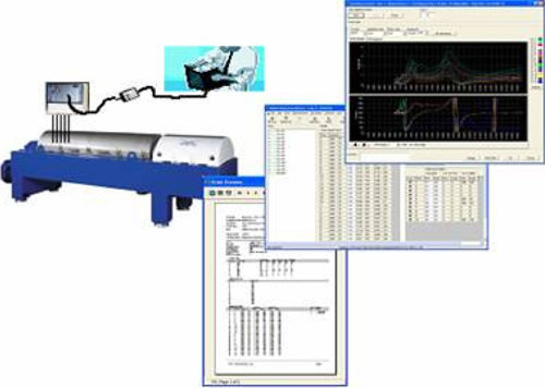
ROBAL® is a software when combined with MIVA® hardware creates an universal, cost-effective solution for balancing both rigid and flexible rotors. The software can be used in the field, during production at the end user and in balancing machines and spin-pits for balancing. All equipment can operate point-to-point with a PC Client or with a Central Computer (MIVA® Data Server) for client-server operation over the LAN and over the Internet, thus providing a general solution for balancing rotating machinery regardless where you are located.
Applications
The MIVA® Rotor Balancing System can be used in:
- Low speed balancing in hard-bearing or soft-bearing balancing machines
- High-speed balancing in a spin-pit or special balancing frames
- Field balancing of fans, high-speed centrifuges, decanter centrifuges etc
- Online balancing of turbine generators, draft induced fans and other machine types
System Configuration for Balancing
Online system
The on-line system can be used in spin-pits and balancing machines. It consist of a MIVA® Data Server (MDS) which is connected to one or several MIVA® Data Acquisition units (DAU). MDS communicates with the DAU over the RS-485 (red). One or more PC Clients can connect to MDS via Ethernet, either locally in the balancing operator room as a work group or within the whole organization as a client on the Corporate LAN.
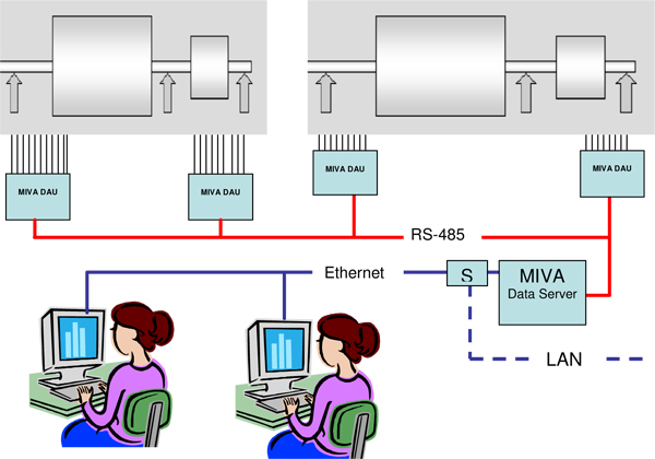
The DAU must be configured for the specific balancing task. A MIVA® 5000 unit with parallel data sampling is recommended when data is captured during start-up and shut down. Sequential sampling may be sufficient if the rotor speed can be controlled.
 The MIVA® Data Server can control several DAU. These should be installed next to the machine or bearings at appropriate locations to minimize the analogue cable length.
Field balancing
Field balancing can be carried out with a Laptop PC connected to a portable DAU (MIVA® 5100 or MIVA® 5100S) or the MIVA® Machine Protector (MMP). MMP, which normally operates standalone for online monitoring can be switched to online mode and used for balancing with a laptop PC and ROBAL®. The PC can be connected to MMP via a USB-2-RS 485 adapter.
The same adapter can also be used for connection to the other portable battery operated DAU units. Note that all portable units provided by VIKON can be interconnected via RS-485, thus providing minimum analogue cabling lengths and simple installation on large turbines and similar machines.
 Online Unbalance Monitoring
A special version of ROBAL® called CUMS (Continuous Unbalance Monitoring) can be installed in the PEMAC® Software for online monitoring of rotor unbalance. Data is acquired continuously and the unbalance is calculated with influence coefficients from ROBAL®. Whenever alarm breaches the machine operator can read the actual unbalance mass and angle and decide if alarm is due to unbalance or other reasons. This allows him to decide and install the correction weights when production allows the machine to be stopped.
 Remote Balancing
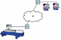
The MIVA® Data Server may be installed in a plant and transmit unbalance response data over the Internet to a PC Client with the ROBAL® Balancing software. This provides a cost-effective system for Servicing machines remotely.
About the ROBAL® Rotor Balancing Software
ROBAL® is a software for rotor balancing developed by VIKON Vibrationskonsult AB. Our aim in designing ROBAL® has been to cover all aspects of balancing. From simple one plane balancing to multiple plane balancing in situations when the number of correction planes far exceeds the number of linearly independent equations visible in the balancing data. ROBAL® is used for field balancing of fans, generator rotors, separators and other rigid rotors requiring only two planes. It has been used successfully in low speed balancing machines for balancing of rigid and also flexible rotors at speeds that is far below the first bending critical. Methods used in ROBAL® are based on theories developed by Dr. Ing. J. Drechsler and Lars Ove Larsson in the early and mid 1970. These methods have been used successfully for balancing of rigid and flexible rotor shafts since mid 1970.
Technical Data
The following basic functions are supported by ROBAL®
- Data collection
- Calculation of the Influence coefficients
- Calculation of the unbalance
- Calculation of the unbalance response
- Print out of reports from balancing
- Export/Import of balancing jobs
- Import of data files from previous ROBAL® versions
The maximum number of balancing planes, measure points and Point-Speed-Vector (PSV) elements are:
| Planes: | 15 |
| Measure points: | 30 |
| PSV elements: | 300 |
Balancing runs and Measurements
 Balancing Run
A run is defined by the initial rotor unbalance, installed external correction weights relative the previous run and the resulting vibration response. A new run is required when weights have been added or removed, or when an apparent change has taken place in the initial unbalance, e.g. due to asymetric machining of the rotor shaft. In this case it is necessary to change identity of the following runs by changing the Group number. This allows available balancing runs to still be used for calculation of the influence matrix.
Measurement
One or more measurements can be made for each balancing run. For instance Measurement 1 could be readings at 0 load, Measurement 2 could be at 50% load and Measurement 3 could be at 100% load. Any one of these or the average of all or some of them can be used as vibration data for the run. This feature is useful when unbalance changes are due to external factors.
Data collection
Data collection is controlled from a separate module in ROBAL® which allows to capture data automatically, on set time intervals or manually. The vibration RMS, 1xN or 2xN components are displayed in real time for each channel.
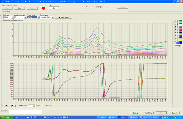
Raw vibration data is stored on files that can be re-imported to ROBAL®. These files can also be created locally in a factory by the MIVA® Data server software and transmitted over e.g. the Internet for import to ROBAL®. Vibration data corresponding to the PSV-elements are stored in the ROBAL® Database and used for calculation of unbalance and influence coefficients. See "Calculation of Unbalance" below..
Influence Coefficient Calculations
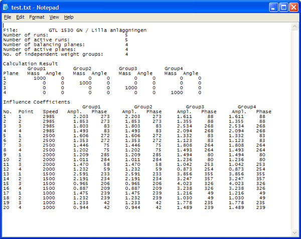
The influence matrix specifies the influence of a group of correction weights on the vibration response. A group may be a weight in a single balancing plane or it could be a group of weights corresponding to a specific modal unbalance component, e.g. first critical. The influence matrix is calculated from all available balancing runs done with the rotor including trial weights in one or more planes and the correction weights installed in order to balance the rotor.
The influence matrix is design-related. Provided the design remains unchanged from a dynamic point of view, the matrix will be the same as well. This offers obvious practical advantages since it permits direct re-balancing with an old influence matrix, without having to perform new test runs. We have cases where an influence matrix calculated years ago still can be used to balance a machine in just a few attempts.
The following example shows a printout of an influence matrix where sufficient linearly independent balancing runs have been made to allow separation of single weights in the balancing planes.
Calculation of Unbalance
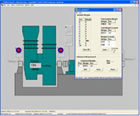
The unbalance is calculated immediately after completion of the balancing run i.e. when the data collection module has been closed. The results are presented in a calculation sheet like the one below.
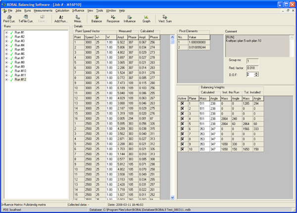
Data captured during the run is averaged within the windows specifying the Point-Speed-Vector element (PSV). Each element is defined by a measure point and a speed window (N ± Drpm). A weight factor W can be set to each PSV element.
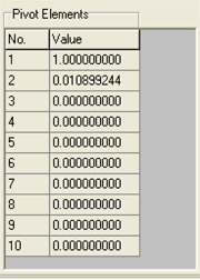
Calculation is governed by the number of degrees of freedom (DOF) and the active balancing planes. Each DOF is related to a particular unbalance mode. The most predominant one is the first one in the list of Pivot elements (1.000000). The Pivot elements indicate how many Linearly Independent Equations (LIEQ) that can be found in data, see next section.
The reduction factor shows the expected reduction of the actual vibration after the calculated weights have been installed. Both the actually measured and the predicted (Calculated) vibration response are shown on the calculation sheet. The sheet also displays totally installed weights.
 The Pivot Element
Values shown under “Pivot Elements” is a unique feature in ROBAL®. Correct interpretation of these values can help you to save considerably time and to avoid unnecessary trial runs.
Balancing is a matter of solving linear equations. One PSV-element represents one equation. From a theoretical point of view this means that you may have as many as 300 equations to solve in order to calculate the unbalance in say 10 planes. From a practical point of view it is very unlikely that all equations are linearly independent. The number of linearly independent equations (LIEQ) depends on the unbalance distribution and on the dynamic properties of the rotor design, support structure and the rotor speed.
When the pivot-element values suddenly drop to zero like in above example it indicates that we have only two LIEQ and thus can balance out two modes only. Trying to balance in more planes than the number of LIEQ will inevitably lead to problems. This is actually a reason for many so called “balancing problems “ where days and weeks have been spent trying to balance a machine.
With ROBAL® you can avoid this problem and balance the rotor in short time regardless. By reducing the degrees of freedom to the number of LIEQ you can still calculate the unbalance correctly in as many planes as you have defined. The picture on the left below shows results with 10 DOF. The one on the right with 2 DOF, which is the true number of LIEQ, shows the correct results. It calculates the weights with respect to the existing modes and minimizes the residual internal bending momentum, that may bend the rotor at higher speeds, above the balancing speed. Thus you will always get the best possible balance quality.
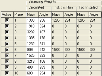 |
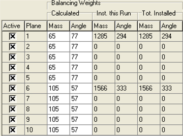 |
| Unbalance calculated with 10 DOF | Unbalance calculated with 2 DOF |